Process modeling fundamentals
In Pega Platform™, a Process is defined as a series of Steps that are expected to occur in a logical, sequential order. Because business processes do not often follow a sequential path towards completion, Pega Platform has implemented the concept of the Process diagram, which allows you to create advanced configurations that control the path a Process takes toward resolution.
In this topic, you examine the relationship between Processes as defined in the Case Lifecycle designer and Process diagrams.
Process diagrams
When a Process is added to a Case Type in the Case Lifecycle designer, the Steps are configured in a logical order that follows the typical sequence to completion for the Process. In order to configure Steps in a Process that deviate from the logical order, you can build advanced configurations by adding shapes to the Process diagram in the Process Modeler.
The Process diagram uses graphical shapes and connectors to define the sequence of events configured for the Process. The shapes and connectors, the link between shapes, depend on the types of Steps that make up the Process and the order in which the Steps occur.
In the center of the following image, slide the vertical line to compare the views of a Process in the Case Lifecycle and the Process diagram:
Just as each type of Step in the Case Lifecycle designer has its icon and color, each shape in the Process diagram has an associated color and shape.
As illustrated in the view of the Case Lifecycle, a green clipboard represents a Collect information Step. The corresponding shape in the view of the Process diagram is a green rectangle. By default, every Process diagram includes a Start shape (green circle) and an End shape (red circle). Complex configurations in a Process diagram include:
- Subprocesses, such as the Approve/Reject Step, which are blue rectangles.
- Automation shapes, such as Create Case, Send email, or Change Stage, which are yellow rectangles.
- Decision shapes which are orange diamonds.
The following topics contains information that is important for your understanding of configuring complex Processes using shapes and connectors and for passing the certification exam: Configuring complex Processes and Process Shapes.
Accessing Process diagrams
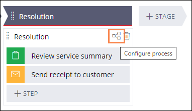
As seen in the following image, you access a Process diagram by clicking the Configure Process icon located in the Process in the Case Lifecycle. This opens the Process Modeler, where you can add, edit, and remove shapes in the Process diagram:
Decision shapes
In Pega Platform, you can model complex Case Lifecycles that require branching or skipping a Step. For example, when a home is above a certain age, it must be tested for lead paint. When a home is below a certain age, it does not need to be tested for lead paint.
Automating these complex decisions based on business logic allows application users to focus on decisions that require human expertise. For example, a loan applicant with a low credit score but a high salary and a passing background check may require a loan officer to assess additional qualifying factors that cannot be automated.
Decision shapes are fundamental to automating complex decisions, allowing you to add a conditional path that supports more than one outcome to a Process diagram. Decision shapes are configured to advance a Process automatically based on business logic or a set of one or more Conditions.
In the following image, click the + icons to learn more about a credit check process that uses a Decision shape to model the conditional Process diagram:
Some variations of the Decision flow include:
- Cases that move forward but may include another Step as needed. You can choose when additional processing is needed to support Case processing.
- Cases that go to another Stage. You can use the Change Stage shape to move a Case to a different Stage in the Case Lifecycle. By skipping a Stage, you can support out-of-sequence processing in a Case.
Flow Actions
Where a Process diagram maps out the path of a Process from beginning to end, Flow Actions define what a user can do at a specific Step within a Process.
Flow Actions control how users interact with forms as they perform an Assignment. For example, in a damaged goods claim process, the buyer can choose to have the goods either reimbursed or replaced. The Flow Actions associated with the choice or either reimbursement or replacement will require different input fields and may use different displays on the form.
Within a Process, you associate a Flow Action with a connector or an Assignment shape. Within a Process diagram, a connector is designated by the arrow between shapes, and an Assignment shape is designated by a green rectangle.
The following image illustrates the connectors and assignment shapes associated with the Process diagram of the Create Stage in the Assistance Request Case Type:

Flow Actions can be either a Connector Action or a Local Action. Connector Actions complete the Assignment and advance the Case to the next shape. Connector Actions are configured as a line shape in the Process Modeler. Local Actions update the Assignment but do not advance the Case to the next shape. Local Actions are configured in the properties pane of an Assignment shape in the Process Modeler.
The following topic contains information that is important for your understanding of Flow Actions and for passing the certification exam: Flow Actions.
Check your knowledge with the following interaction:
このトピックは、下記のモジュールにも含まれています。
トレーニングを実施中に問題が発生した場合は、Pega Academy Support FAQsをご確認ください。